Analytical and experimental analyses of the out-of-plane response of clay brick masonry in earthquakes
 Photo/Foto: IZF/TU Kaiserslautern
 Photo/Foto: IZF/TU Kaiserslautern
![»3 Damage following an earthquake [14]](https://www.zi-online.info/imgs/1/7/0/1/3/6/7/3-6d63971473ab3b0d.jpeg) Photo/Foto: [14] Angelo Giordano
Photo/Foto: [14] Angelo Giordano
![»4 Spatial distribution of the spectral response acceleration for the subsurface condition A-R in the plateau zone SaP,R for a return period TNCR = 475 years [2]](https://www.zi-online.info/imgs/1/7/0/1/3/6/7/4-10b70723800ae8d7.jpeg) Photo/Foto: IZF/TU Kaiserslautern
Photo/Foto: IZF/TU Kaiserslautern
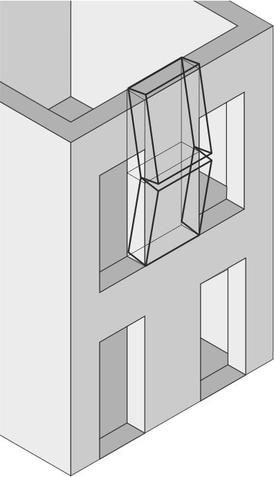
![»5 Analytical model after Lönhoff/Helm [8–11]](https://www.zi-online.info/imgs/1/7/0/1/3/6/7/5-6e6f8ef7d1ae9928.jpeg) Photo/Foto: IZF/TU Kaiserslautern
Photo/Foto: IZF/TU Kaiserslautern
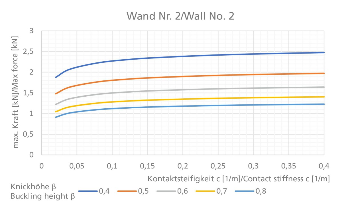
![»6a, b,c The absorbable force determined with the Lönhoff/Helm model [8–11] as a function of the contact stiffness and buckling height for three walls](https://www.zi-online.info/imgs/1/7/0/1/3/6/7/6a-55dbdf2725a98a03.jpeg) Photo/Foto: IZF/TU Kaiserslautern
Photo/Foto: IZF/TU Kaiserslautern
 Photo/Foto: IZF/TU Kaiserslautern
 Photo/Foto: IZF/TU Kaiserslautern
 Photo/Foto: IZF/TU Kaiserslautern
![»8 Bending stress after DIN EN 1052-2 [15] parallel and perpendicular to the bed joint](https://www.zi-online.info/imgs/1/7/0/1/3/6/7/8-4232cfe01ad8911f.jpeg) Photo/Foto: IZF/TU Kaiserslautern
Photo/Foto: IZF/TU Kaiserslautern
 Photo/Foto: IZF/TU Kaiserslautern
 Photo/Foto: IZF/TU Kaiserslautern
 Photo/Foto: IZF/Etscheid
 Photo/Foto: IZF/Etscheid
 Photo/Foto: TU Kaiserslautern/Sadegh-Azar
 Photo/Foto: TU Kaiserslautern/Helm
For those regions of Germany with a high earthquake risk, since the introduction of the DIN 4149 standard in 2005, proof of structural stability of buildings in the event of earthquakes must be provided. In cooperation between the Brick and Tile Research Institute Essen (IZF) and Technical University Kaiserslautern (TUK), the out-of-plane response of brick masonry has been studied with the goal of developing a cost-effective design concept for determination of the out-of-plane load capacity under earthquake load.
For design with the newly developed realistic analytical model, amongst other things, the buckling height β and the contact stiffness c, an auxiliary coefficient defined in the model, must be presumed. In the following, a sensitivity analysis in respect of the effects of the above-mentioned parameters on the out-of-plane load capacity is presented. In addition, series of tests on a four-point bending test rig are described for characterization of the contact stiffness.
1 Introduction
Masonry construction is one of the oldest building methods worldwide and remains a very common building technique in traditional building construction. Particularly for vertical load transfer, masonry exhibits excellent properties. Under the impact of earthquakes, however, repeated structural failure has been observed worldwide, as masonry can absorb only limited horizontal loads. To absorb loads caused by seismic impact in a building, the in-plane load-bearing capacity of masonry is utilized, with which the load is transferred in the plane of the load-bearing wall. As a result of the inertia of the wall, earthquake excitation, however, generates large loads perpendicular to the plane (out-of-plane). Impacting the wall is therefore a base excitation, which is idealized as horizontal line load and as a result of which the wall fails out of plane (»1, »2, »3). The out-of-plane response describes this potential failure mode, which has been a key aspect of international research projects for many years.
In the case of an uncracked wall, the flexural strength of the mortar or the masonry first bears any loads. As particularly in the case of mortar, the tensile strength is low for many types of wall, in most models it is assumed that this is exceeded and gaping joints as well as large deformations are allowed to form. The remaining load-bearing capacity is calculated from the self-weight and external boundary conditions. For example, as the result of a floor, a sort of structural arching action is activated, as a result of which higher loads can be absorbed.
The loads that have to be expected as a result of earthquakes in Germany have been regulated in the standard DIN 4149 [1] since its introduction in 2005. Since then, verification of structural integrity in the event of earthquakes is required in those regions of Germany exposed to seismic risk. With the new national annex of DIN EN 1998-1 [2] and its planned technical approval, new seismic risk maps for Germany will apply (»4), which will further increase the accelerations to be taken into account in the design and appraisal of building structures in many regions.
In the currently applicable standards, DIN EN 1996 [3] and DIN EN 1998 [4], there are models and rules for the load capacity of masonry perpendicular to the plane. In Germany, certification methods explicitly intended for the out-of-plane response of masonry walls can only be found in the directive of the Nuclear Safety Standards Commission KTA 2201.3 [5]. The analytical model described in KTA 2201.3 is based on the static arching action of the masonry between sufficiently rigid supports, the monoaxial load transfer being either horizontal or vertical. Moreover, to ensure force transmission, a full mortaring of the cross or vertical joints over the complete thickness of the wall is required and the compressive and shear stresses at the support certified.
Especially for slender non-load-bearing interior partition walls, the regulations are often not practicable or applicable. Lacking is a design concept regulated in a standard to enable cost-efficient verification. Consequently, the use of brick masonry is made difficult in regions with increased earthquake risk so that other alternative building materials are chosen. Even for existing masonry structures, subsequent cost-intensive reinforcement measures can be required.
The studies presented here were compiled in the scope of the AiF research project “Development of a realistic design concept for the out-of-plane load capacity of unreinforced masonry walls for the reduction of conserving measures”. The project was conducted in cooperation between the Brick and Tile Research Institute Essen (IZF) and Technical University Kaiserslautern (TUK) and funded by Germany’s Federal Ministry for Economic Affairs and Energy, pursuant to a resolution passed by the German Parliament under IGF project No.: 19851 N.
2 Analytical calculations of the out-of-plane load capacity
In practice, models from the relevant literature (e.g. Paulay/Priestley [6] and Doherty/Griffith [7]) are applied. In the Paulay/Priestley model dating from 1992, the wall is divided into two equisized rigid shear sections and loaded by the maximum acceleration of the floor. To determine the load-bearing capacity, first an equilibrium analysis at the centre of the wall is applied, the self-weight and an applied load being taken into consideration. Finally, from the non-linear system, the elastic response acceleration is determined, with the approach that this generates the same strain energy. In the Doherty/Griffith model from 2002, the wall is also divided into two rigid shear sections. With the help of equilibrium considerations and experimentally determined factors, a trilinear force-deformation relationship is defined.
Despite the relevance for building practice, no uniform model for the calculation of load capacity has so far been established. Analytical studies at the TUK have shown that the prediction of the out-of-plane load capacity with existing methods shows wide variation. Furthermore, experimental studies have shown that the actually observed dynamic load-bearing capacity is often higher than predicted. The reason for this is that in most models, the vertical stiffness identified as a key influencing factor in the studies is not taken into account. Parameters such as buckling height, the centre of rotations and other factors are only considered in a simplified way. On the basis of these simplifications, a realistic analytical model incorporating all key influencing factors is developed [8–11]. For this, the Paulay and Priestley model [6] as well as the Doherty and Griffith model [7] are used as a basis, and the structural arching action considered based on a vertical stiffness of the support at the top of the wall.
Basis of model is formed by two rigid shear sections (»5), their size being defined based on the buckling height β. The contact of the sections between each other is reproduced with an elastic support. Further, various external boundary conditions, e.g. contact to a reinforced concrete floor or an applied load, at the top of the wall are taken into consideration.
For description of the elastic support, the contact between the rigid sections, an auxiliary coefficient is introduced: The auxiliary coefficient
c = 1/l
is defined as the inverse of the length of the contact springs and is termed the contact stiffness in the following. With the auxiliary coefficient, the behaviour of different types of wall and the degree of damage can be represented.
First the static force-deformation relationship of the uniaxially stressed unreinforced masonry wall is determined with consideration of the real deformations, based on the principle of virtual work. For the dynamic calculation, a strongly non-linear and time-dependent process, the wall is idealized as an equivalent simple mass oscillator, with which a time curve is calculated. With the realistic model, displacement of the wall as a result of a design-basis earthquake is calculated, and this is verified based on calculations. For this, the dimensions, the weight and the boundary conditions at the top of the wall must be known. In addition, three values must be presumed: the buckling height, the contact stiffness and the damping.
The buckling height is either calculated with the help of the elastic beam theory or presumed based on experimentally determined factors. The point at which the buckling height actually takes effect depends on the scattering of the flexural strength, which cannot be determined in advance. The buckling height also has a considerable influence on the load capacity of the wall. Because of this relationship, there results an inaccuracy in the design that cannot be avoided.
The contact stiffness and damping cannot currently be determined with analytical models and therefore for a more precise quantification of the two parameters, test data for various wall-mortar combinations are necessary. The question is how high the influence of the two parameters on the load-bearing capacity is in relationship to the buckling height, which is subject to wide variation, and how precisely these values need to be determined in tests for the purpose of reliable design. In the following, this correlation is investigated for the contact stiffness.
3 Sensitivity analysis with the buckling height and contact stiffness
While the damping has an influence on the dynamic load capacity, the buckling height and the contact stiffness already influence the force-deformation curve of the wall. Accordingly, the buckling height and the contact stiffness can be easily contrasted by comparing the maximum static forces.
The buckling height β, defined as a wall height factor, varies in an overview of tests according to [12] between β = 0.52 and 0.71, the mean here being 0.593. To take the probability distribution into account, the 5 % and 95 % quantile are calculated and these result in the threshold values Qß0,05 = 0,55 and Qß0,95 = 0,65. In a series of tests conducted at the TUK with eight walls, a similar range of values of β = 0.45 – 0.67 resulted. For the contact stiffness, on account of a lack of test data, no substantiated values can be given. Initial tests at the TUK have shown that small values of c = 0.008 1/m are possible for damaged walls [8]. A comparison with test data according to [13] suggests values around c = 0.25 1/m. Current investigations at the TUK with vertically perforated clay blocks confirm a higher value range of 0.13 – 0.4 1/m.
The two parameters are contrasted based on three generic examples by calculating the load capacity of the walls with the Lönhoff/Helm model. »Table 1 lists the wall properties and Figs. »6 a, b and c show the results.
The thickness of the second wall is increased in comparison with the first wall from 11.5 cm to 24 cm. For both walls, the load capacity increases with a lower buckling height. For the 95 % quantile, there results for both walls, independent of the contact stiffness, a deviation in the load capacity of around 20 % relative to the 5 % quantile. For wall design, to be on the safe side, a buckling height of Qß0,95 = 0,65 should be chosen for this type of wall.
For the third wall, it is assumed that the top of the wall is mortar-bonded over the entire surface area with a reinforced concrete floor. For this wall, buckling in the middle of the wall is most unfavourable. If here too, for better estimation, the quantiles for the buckling height are used, a maximum deviation in the load capacity of 24 % results. If a vertical stiffness, which has a major influence on the load capacity, is taken into consideration, then the lower buckling height of Qß0,05 = 0,55 can be recommended for design.
For all three walls, the load capacity falls with lower contact stiffness. For the value range from von c = 0.02 – 0.40 1/m in question, for the first wall, at each buckling height there results a deviation of 75 – 85 % in the load capacity. For the second less slender wall, the deviation, in contrast, is only 32 – 35 %. Accordingly, the sensitivity appears to be directly related to the wall thickness or slenderness. For the third wall, there is a pronounced relationship with the buckling height, here the deviation for the quantiles Qß0,05 and Qß0,95 varies from 39 – 53 %.
The sensitivity analysis shows that the load capacity varies widely on account of the existing imprecision, and a more precise quantification of the contact stiffness is essential for reliable design. Especially for cost-effective design of slender walls, a lower limit must be determined.
4 Cyclic bending tests on brick masonry for
determination of the contact stiffness
As explained earlier, the existing contact stiffness represents a significant as well as necessary variable in connection with the out-of-plane-load capacity and its design. Further, it could be shown that with the current analytical models it is not possible to determine the contact stiffness, so that experimental investigations must be conducted for this purpose.
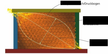
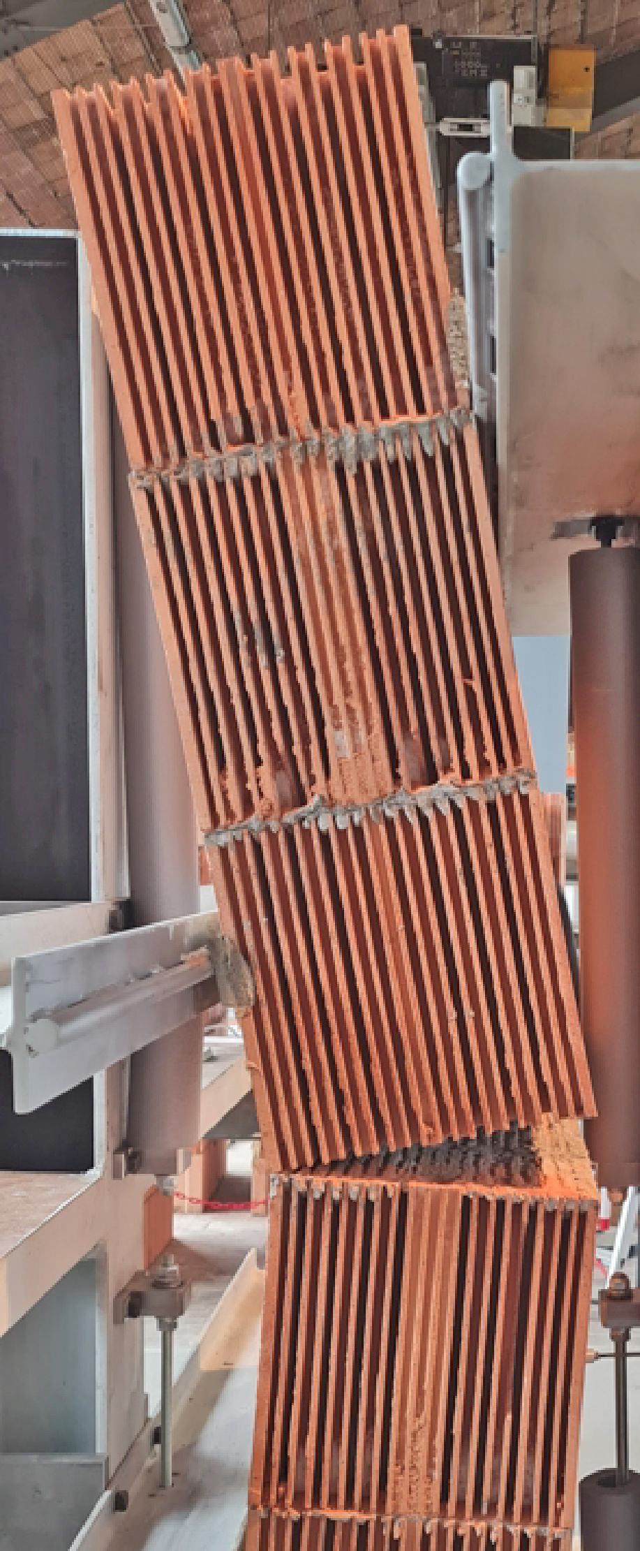
If a masonry wall is exposed to a horizontal load caused by an earthquake or, for example, wind, earth pressure or impact, the existing flexural strength in the uncracked state of the wall presents resistance. Depending on the prevailing load transfer, in the masonry flexural stresses result from the horizontal load parallel or perpendicular to the bed joint, from which different fracture planes result. The experimental determination of the flexural strength on small masonry specimens is conducted in compliance with DIN EN 1052-2 [15] with the application of a four-point load. For this purpose, a four-point bending test rig is available at the Brick and Tile Research Institute in Essen (IZF) with which bending stresses can be applied both parallel and perpendicular to the bed joint up to failure of the masonry specimen (»7).
For testing flexural strength in compliance with DIN EN 1052-2 [15], small-size test specimens, usually in a vertical position, are tested to failure under a defined four-point load. The supports must be configured such that the load is both introduced and transferred over the entire width of the test specimen. After the test has been completed, from the determined maximum fracture load, with allowance for the respective test specimen dimensions and the inner and outer support spans, the flexural strength of the masonry specimen is calculated. If this is determined in vertical position in accordance with DIN EN 1052-2 [15], the support at the foot of the wall must be designed to be frictionless as far as possible, as a result of which at this a point of zero moment results while there is a constant maximum moment between the inner supports. Fig. »8 shows schematically the different arrangements of the supports and the load introduction areas with the fracture plane parallel and vertical to the bed joint.
If the flexural strength of the masonry specimen is exceeded, a gaping joint forms, which corresponds to the classical out-of-plane failure mode (»1, »2, »5). The remaining out-of-plane load capacity now depends on various parameters such as the wall’s self-weight, the buckling height, effective vertical loads, contact to a reinforced concrete floor and the contact stiffness. The latter describes more exactly the contact stiffness (elastic support) between the two rigid wall sections that form within the out-of-plane failure mode (»5). To define the contact stiffness especially of brick masonry more precisely, various test series were conducted on the four-point bending test rig.
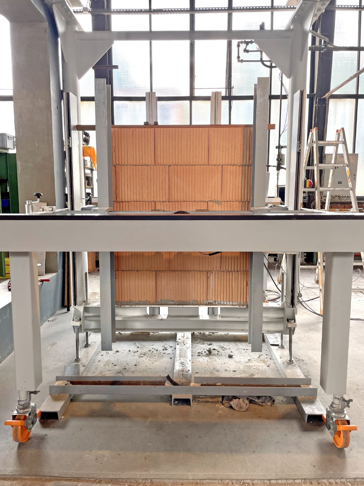
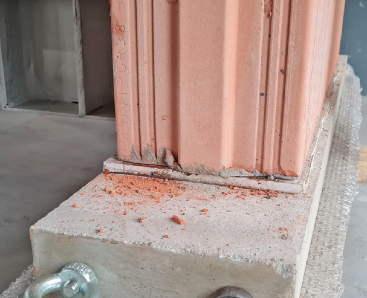
In comparison with the described testing methods for determination of the flexural strength in compliance with DIN EN 1052-2 [15], in the tests for determination of the existing contact stiffness, certain modifications were made. First, the form of the wall foot point was adjusted from a flexible almost frictionless support to the real conditions that would be found existing in a building. For this, the masonry walls to be tested were positioned over their entire surface on corresponding concrete foundations (»9), as a result of which the typical out-of-plane mode of failure on the cracked masonry specimens ensues.
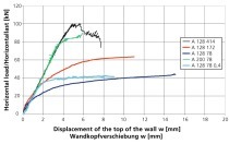
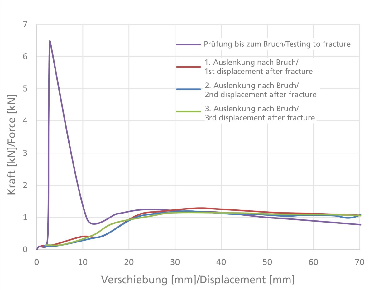
On the other hand, so-called pushover tests were conducted. In these tests, the masonry wall is first loaded up to fracture and the occurrence of the gaping joint. After onset of the out-of-plane failure modes in the tested masonry walls (»2), the cracked walls were displaced in a strain-controlled process by a defined degree ∆ and the associated necessary horizontal force applied was plotted. As earthquake events are cyclic loads, the displacements of the cracked walls were performed several times in succession. After the maximum tested displacement is achieved, which lies at the half wall thickness to avoid stability failure, the wall was brought back to the starting position so that ∆ = 0 applies. »10 shows the force-deformation behaviour determined in this way of a tested 17.5-cm-thick wall built with vertically perforated clay blocks for three consecutive displacements by 70 mm and the initial fracture. For this wall made of vertically perforated bricks, the maximum breaking load determined according to DIN EN 1052-2 [15] results in a bending tensile strength fxi of 0.33 N/mm² for a bending load perpendicular to the bearing joint. If the characteristic bending tensile strength fxk is calculated from this single value, a value of 0.22 N/mm² is obtained, which corresponds to the results according to [16] for brick masonry with thin-bed mortar.
If the three different force-deformation curves of the conducted displacements are examined, identical behaviour can be identified. Both for the displacement after the initial fracture, as well as in the three further cyclic deflections, the same applied force is shown. On the basis of the force-deformation behaviour determined in this way, the contact stiffness of brick masonry necessary for the engineering model is characterized with the help of analytical evaluations.
5 Summary and outlook
Masonry construction is widespread and commonly used building method in building construction today. With the regard to the vertical load transfer, masonry exhibits very positive properties. In contrast, behaviour when exposed to the effect of horizontal loads, e.g. as a result of seismic impact, that is so-called out-of-plane behaviour, is largely still unknown and is not realistically estimated in analytical models. To better simulate the out-of-plane behaviour of brick masonry during earthquakes, a novel engineering model has been established that takes into account all major influencing factors for uniaxial load transfer.
For design with the newly developed realistic analytical model, amongst other things the buckling height β and the contact stiffness c, an auxiliary value defined in the model, must be presumed. A sensitivity analysis has shown that the load capacity varies widely on account of the existing imprecision, such that a more precise quantification of the contact stiffness is essential for reliable design. For this reason, for verification of the model and for determination of the contact stiffness defined in the model, pushover tests were planned and conducted. For this purpose, brick walls were loaded under a horizontal load until fracture occurred. To analyse the load behaviour of cracked walls, the walls were cyclically pushed and the force necessary for displacement recorded.
For further verification of the postulated engineering model, the pushover tests are being modified further and the test boundary conditions adapted in respect of horizontal impact, support as well as vertical load to realistic installation situations. Consequently, a well-founded quantification of the contact stiffness will be possible in future. In further test series, tests on brick walls on a shaking table are being conducted with earthquake loads. In addition, the engineering model is being extended to make provision for biaxial load transfer.
wänden unter Erdbebeneinwirkung [Dissertation]. TU Kaiserslautern.